Tag Archives: Empa

Slowly crossing the valley of death

A view of a valley
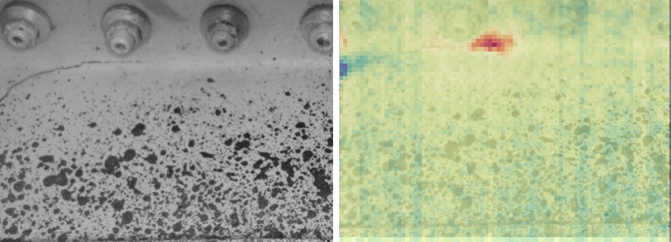
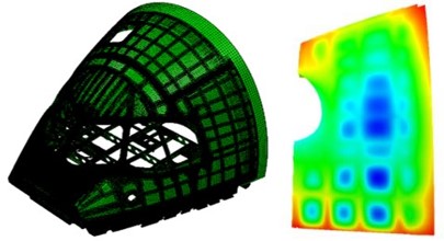
The valley of death in technology development is well-known amongst research engineers and their sponsors. It is the gap between discovery and application, or between realization of an idea in a laboratory and its implementation in the real-world. Some of my research has made it across the valley of death, for example the poleidoscope about 15 years ago (see ‘Poleidoscope (=polariscope+kaleidoscope)‘ on October 14th, 2020).  Our work on quantitative comparisons of data fields from physical measurements and computer predictions is about three-quarters of the way across the valley.  We published a paper in December (see Dvurecenska et al, 2020) on its application to a large panel from the fuselage of an aircraft based on work we completed as part of the MOTIVATE project.  I reported the application of the research in almost real-time in a post in December 2018 (see ‘Industrial Uncertainty‘ on December 12th, 2018) and in further detail in May 2020 as we submitted the manuscript for publication (‘Alleviating industrial uncertainty‘ on May 13th, 2020).  However, the realization in the laboratory occurred nearly a decade ago when teams from Michigan State University and the University of Liverpool came together in the ADVISE project funded by EU Framework 7 programme (see Wang et al, 2011). Subsequently, the team at Michigan State University moved to the University of Liverpool and in collaboration with researchers at Empa developed the technique that was applied in the MOTIVATE project (see Sebastian et al 2013). The work published in December represents a step into the valley of death; from a university environment into a full-scale test laboratory at Empa using a real piece of aircraft.  The MOTIVATE project involved a further step to a demonstration on an on-going test of a cockpit at Airbus which was also reported in a post last May (see ‘The blind leading the blind‘ on May 27th, 2020).  We are now working with Airbus in a new programme to embed the process of quantitative comparison of fields of measurements and predictions into their routine test procedures for aerospace structures.  So, I would like to think we are climbing out of the valley.

Image: not Death Valley but taken on a road trip in 2008 somewhere between Moab, UT and Kanab, UT while living in Okemos, MI.

Sources:

Dvurecenska, K., Diamantakos, I., Hack, E., Lampeas, G., Patterson, E.A. and Siebert, T., 2020. The validation of a full-field deformation analysis of an aircraft panel: A case study. The Journal of Strain Analysis for Engineering Design, p.0309324720971140.

Sebastian, C., Hack, E. and Patterson, E., 2013. An approach to the validation of computational solid mechanics models for strain analysis. The Journal of Strain Analysis for Engineering Design, 48(1), pp.36-47.

Wang, W., Mottershead, J.E., Sebastian, C.M. and Patterson, E.A., 2011. Shape features and finite element model updating from full-field strain data. International Journal of Solids and Structures, 48(11-12), pp.1644-1657.

For more posts on the MOTIVATE project: https://realizeengineering.blog/category/myresearch/motivate-project/

The MOTIVATE project has received funding from the Clean Sky 2 Joint Undertaking under the European Union’s Horizon 2020 research and innovation programme under grant agreement No. 754660 and the Swiss State Secretariat for Education, Research and Innovation under contract number 17.00064.

The opinions expressed in this blog post reflect only the author’s view and the Clean Sky 2 Joint Undertaking is not responsible for any use that may be made of the information it contains.

Most valued player performs remote installation

Our Most Valued Player (inset) installing a point sensor in the front section of a fuselage at Airbus in Toulouse under the remote direction of engineers in Switzerland and the UKMany research programmes have been derailed by the pandemic which has closed research laboratories or restricted groups of researchers from working together to solve complex problems. Some research teams have used their problem-solving skills to find new ways of collaborating and to continue to make progress. In the DIMES project we have developed an innovative system for detecting and monitoring the propagation of damage in aircraft structures, and prior to the pandemic, we were planning to demonstrate it on a full-scale test of an aircraft fuselage section at Airbus in Toulouse. However, the closure of our laboratories and travel restrictions across Europe have made it impossible for members of our team based in Liverpool, Chesterfield, Ulm and Zurich to meet or travel to Toulouse to set-up the demonstration. Instead we have used hours of screen-time in meetings to complete our design work and plan the installation of the system in Toulouse. These meetings often involve holding components up to our laptop cameras to show one another what we are doing.  The components of the system were manufactured in various locations before being shipped to Empa in Zurich where they were assembled and the complete system was then shipped to Toulouse.  At the same time, we designed a communication system that included a headset with camera, microphone and earpieces so that our colleague in Toulouse could be guided through the installation of our system by engineers in Germany, Switzerland and the UK.  Amazingly, it all worked and we were half-way through the installation last month when a rise in the COVID infection rate caused a shutdown of the Airbus site in Toulouse.  What we need now is remote-controlled robot to complete the installation for us regardless of COVID restrictions; however, I suspect the project budget cannot afford a robot sufficiently sophisticated to replace our Most Valued Player (MVP) in Toulouse.

The University of Liverpool is the coordinator of the DIMES project and the other partners are Empa, Dantec Dynamics GmbH and Strain Solutions Ltd.

Logos of Clean Sky 2 and EUThe DIMES project has received funding from the Clean Sky 2 Joint Undertaking under the European Union’s Horizon 2020 research and innovation programme under grant agreement No. 820951.  The opinions expressed in this blog post reflect only the author’s view and the Clean Sky 2 Joint Undertaking is not responsible for any use that may be made of the information it contains.

Image: Our Most Valued Player (inset) installing a point sensor in the front section of a fuselage at Airbus in Toulouse under the remote direction of engineers in Switzerland and the UK.

Condition-monitoring using infrared imaging

If you have travelled in Asia then you will probably have experienced having your health monitored by infrared cameras as you disembarked from your flight.  It has been common practice in many Asian countries since long before the COVID-19 pandemic and perhaps will become more usual elsewhere as a means of easily identifying people with symptoms of a fever that raises their body temperature.  Since, research has shown that infrared thermometers are slightly more responsive as well as quicker and easier to use than other types of skin surface thermometers [1].  In my research group, we have been using infrared cameras for many years to monitor the condition of engineering structures by evaluating the distribution of load or stress in them [see ‘Counting photons to measure stress‘ on November 18th, 2015 and  ‘Insidious damage‘ on December 2nd, 2015].  In the DIMES project, we have implemented a low-cost sensor system that integrates infrared and visible images with information about applied loads from point sensors, which allows the identification of initiation and tracking of damage in aircraft structures [2].  I reported in December 2019 [see ‘When seeing nothing is a success‘] that we were installing prototype systems in a test-bench at Empa.  Although the restrictions imposed by the pandemic have halted our tests, we were lucky to obtain data from our sensors during the propagation of damage in the section of wing at Empa before lockdown.  This is a landmark in our project and now we are preparing to install our system in test structures at Airbus once the pandemic restrictions are relaxed sufficiently.  Of course, we will also be able to use our system to monitor the health of the personnel involved in the test (see the top image of one of my research team) as well as the health of the structure being tested – the hardware is the same, it’s just the data processing that is different.

The image is a composite showing images from a visible camera (left) and processed data from infrared camera overlaid on the same visible image (right) from inside a wing box during a test at Empa with a crack extending from left to right with its tip surrounded by the red area in the right image.  Each nut in the image is about 20 mm in diameter and a constant amplitude load at 1.25 Hz was being applied causing a wing tip displacement of 80 mm +/- 15 mm.

The University of Liverpool is the coordinator of the DIMES project and the other partners are Empa, Dantec Dynamics GmbH and Strain Solutions Ltd.

The DIMES project has received funding from the Clean Sky 2 Joint Undertaking under the European Union’s Horizon 2020 research and innovation programme under grant agreement No. 820951.


The opinions expressed in this blog post reflect only the author’s view and the Clean Sky 2 Joint Undertaking is not responsible for any use that may be made of the information it contains.

References

[1] Burnham, R.S., McKinley, R.S. and Vincent, D.D., 2006. Three types of skin-surface thermometers: a comparison of reliability, validity, and responsiveness. American journal of physical medicine & rehabilitation, 85(7), pp.553-558.

[2] Middleton, C.A., Gaio, A., Greene, R.J. and Patterson, E.A., 2019. Towards automated tracking of initiation and propagation of cracks in aluminium alloy coupons using thermoelastic stress analysis. Journal of Nondestructive Evaluation, 38(1), p.18.

The blind leading the blind

Three years after it started, the MOTIVATE project has come to an end [see ‘Getting smarter’ on June 21st, 2017].  The focus of the project has been about improving the quality of validation for predictions of structural behaviour in aircraft using fewer, better physical tests.  We have developed an enhanced flowchart for model validation [see ‘Spontaneously MOTIVATEd’ on June 27th, 2018], a method for quantifying uncertainty in measurements of deformation in an industrial environment [see ‘Industrial uncertainty’ on December 12th, 2018] and a toolbox for quantifying the extent to which predictions from computational models represent measurements made in the real-world [see ‘Alleviating industrial uncertainty’ on May 13th, 2020].  In the last phase of the project, we demonstrated all of these innovations on the fuselage nose section of an aircraft.  The region of interest was the fuselage skin behind the cockpit window for which the out-of-plane displacements resulting from an internal pressurisation load were predicted using a finite element model [see ‘Did cubism inspire engineering analysis?’ on January 25th, 2017].  The computational model was provided by Airbus and is shown on the left in the top graphic with the predictions for the region of interest on the right.  We used a stereoscopic imaging system  to record images of a speckle pattern on the fuselage before and after pressurization; and from these images, we evaluated the out-of-plane displacements using digital image correlation (DIC) [see ‘256 shades of grey‘ on January 22, 2014 for a brief explanation of DIC].  The bottom graphic shows the measurements being made with assistance from an Airbus contractor, Strain Solutions Limited.  We compared the predictions quantitatively against the measurements in a double-blind process which meant that the modellers and experimenters had no access to one another’s results.  The predictions were made by one MOTIVATE partner, Athena Research Centre; the measurements were made by another partner, Dantec Dynamics GmbH supported by Strain Solutions Limited; and the quantitative comparison was made by the project coordinator, the University of Liverpool.  We found that the level of agreement between the predictions and measurements changed with the level of pressurisation; however, the main outcome was the demonstration that it was possible to perform a double-blind validation process to quantify the extent to which the predictions represented the real-world behaviour for a full-scale aerospace structure.

The content of this post is taken from a paper that was to be given at a conference later this summer; however, the conference has been postponed due to the pandemic.  The details of the paper are: Patterson EA, Diamantakos I, Dvurecenska K, Greene RJ, Hack E, Lampeas G, Lomnitz M & Siebert T, Application of a model validation protocol to an aircraft cockpit panel, submitted to the International Conference on Advances in Experimental Mechanics to be held in Oxford in September 2021.  I would like to thank the authors for permission to write about the results in this post and Linden Harris of Airbus SAS for enabling the study and to him and Eszter Szigeti for providing technical advice.

For more on the validation flowchart see: Hack E, Burguete R, Dvurecenska K, Lampeas G, Patterson E, Siebert T & Szigeti, Steps towards industrial validation experiments, In Multidisciplinary Digital Publishing Institute Proceedings (Vol. 2, No. 8, p. 391) https://www.mdpi.com/2504-3900/2/8/391

For more posts on the MOTIVATE project: https://realizeengineering.blog/category/myresearch/motivate-project/

The MOTIVATE project has received funding from the Clean Sky 2 Joint Undertaking under the European Union’s Horizon 2020 research and innovation programme under grant agreement No. 754660 and the Swiss State Secretariat for Education, Research and Innovation under contract number 17.00064.

The opinions expressed in this blog post reflect only the author’s view and the Clean Sky 2 Joint Undertaking is not responsible for any use that may be made of the information it contains.