Tag Archives: fatigue

Crack tip plasticity in reactor steels

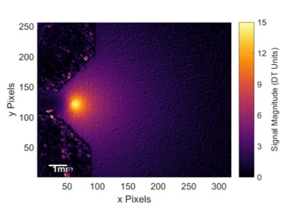
Amplitude of temperature in steel due to a cyclic load with a crack growing from left to right along the horizontal centre line with the stress concentration at its tip exhibiting the peak values. The wedge shapes in the left corners are part of the system.

At this time of year the flow into my inbox is augmented daily by prospective PhD students sending me long emails describing how their skills, qualifications and interests perfectly match the needs of my research group, or sometimes someone else’s group if they have not been careful in setting up their mass mailing.  At the moment, I have four PhD projects for which I am looking for outstanding students; so, because it will help prospective students and might interest my other readers but also because I am short of ideas for the blog, I plan to describe one project per week for the next month.

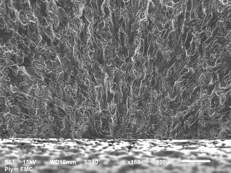
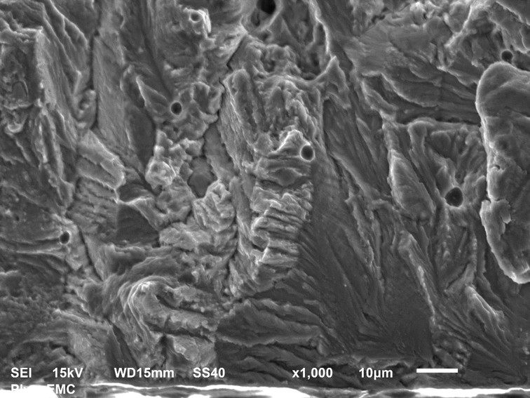
The first project is about the effect of hydrogen on crack tip plasticity in reactor steels.  Fatigue cracks grow in steels by coalescing imperfections in the microstructure of the material until small voids are formed in areas of high stress.  When these voids connect together a crack is formed.  Repeated loading and unloading of the material provides the energy to move the imperfections, known as dislocations, and geometric features in structures are stress concentrators which focus this energy causing cracks to be formed in their vicinity.  The movement of dislocations causes permanent, or plastic deformation of the material.  The sharp geometry of a crack tip becomes a stress concentrator creating a plastic zone in which dislocations pile up and voids form allowing the crack to extend [see post on ‘Alan Arnold Griffith‘ on April 26th, 2017].  It is possible to detect the thermal energy released during plastic deformation using a technique known as thermoelastic stress analysis [see ‘Counting photons to measure stress‘ on November 18th 2015] as well as to measure the stress field associated with the propagating crack [1].  One of my current PhD students has been using this technique to investigate the effect of irradiation damage on the growth of cracks in stainless steel used in nuclear reactors.  We use an ion accelerator at the Dalton Cumbrian Facility to introduce radiation damage into specimens the size of a postage stamp and afterwards apply cyclic loads and watch the fatigue crack grow using our sensitive infra-red cameras.  We have found that the irradiation reduced the rate of crack growth and we will be publishing a paper on it shortly [and a PhD thesis].  In the new project, our industrial sponsors want us to explore the effect of hydrogen on crack growth in irradiated steel, because the presence of hydrogen is known to accelerate fatigue crack growth [2] which is believe to happen as a result of hydrogen atoms disrupting the formation of dislocations at the microscale and localising plasticity at crack tip on the mesoscale.  However, these ideas have not been demonstrated in experiments, so we plan to do this using thermoelastic stress analysis and to investigate the combined influence of hydrogen and irradiation by developing a process for pre-charging the steel specimens with hydrogen using an electrolytic cell and irradiating them using the ion accelerator.  Both hydrogen and radiation are present in a nuclear reactor and hence the results will be relevant to predicting the safe working life of nuclear reactors.

The PhD project is fully-funded for UK and EU citizens as part of a Centre for Doctoral Training and will involve a year of specialist training followed by three years of research.  For more information following this link.

References:

  1. Yang, Y., Crimp, M., Tomlinson, R.A., Patterson, E.A., 2012, Quantitative measurement of plastic strain field at a fatigue crack tip, Proc. R. Soc. A., 468(2144):2399-2415.
  2. Matsunaga, H., Takakuwa, O., Yamabe, J., & Matsuoka, S., 2017, Hydrogen-enhanced fatigue crack growth in steels and its frequency dependence. Phil. Trans. R. Soc. A, 375(2098), 20160412

Red to blue

Some research has a very long incubation time.  Last month, we published a short paper that describes the initial results of research that started just after I arrived in Liverpool in 2011.  There are various reasons for our slow progress, including our caution about the validity of the original idea and the challenges of working across discipline boundaries.  However, we were induced to rush to publication by the realization that others were catching up with us [see blog post and conference paper].  Our title does not give much away: ‘Characterisation of metal fatigue by optical second harmonic generation‘.

Second harmonic generation or frequency doubling occurs when photons interact with a non-linear material and are combined to produce new photons with twice the energy, and hence, twice the frequency and half the wavelength of the original photons.  Photons are discrete packets of energy that, in our case, are supplied in pulses of 2 picoseconds from a laser operating at a wavelength of 800 nanometres (nm).  The photons strike the surface, are reflected, and then collected in a spectrograph to allow us to evaluate the wavelength of the reflected photons.  We look for ones at 400 nm, i.e. a shift from red to blue.

The key finding of our research is that the second harmonic generation from material in the plastic zone ahead of a propagating fatigue crack is different to virgin material that has experienced no plastic deformation.  This is significant because the shape and size of the crack tip plastic zone determines the rate and direction of crack propagation; so, information about the plastic zone can be used to predict the life of a component.  At first sight, this capability appears similar to thermoelastic stress analysis that I have described in Instructive Update on October 4th, 2017; however, the significant potential advantage of second harmonic generation is that the component does not have to be subject to a cyclic load during the measurement, which implies we could study behaviour during a load cycle as well as conduct forensic investigations.  We have some work to do to realise this potential including developing an instrument for routine measurements in an engineering laboratory, rather than an optics lab.

Last week, I promised weekly links to posts on relevant Thermodynamics topics for students following my undergraduate module; so here are three: ‘Emergent properties‘, ‘Problem-solving in Thermodynamics‘, and ‘Running away from tigers‘.


Instructive Update

Six months ago I wrote about our EU research project, called INSTRUCTIVE, and the likely consequences of Brexit for research [see my post: ‘Instructive report and Brexit‘ on March 29th, 2017].  We seem to be no closer to knowing the repercussions of Brexit on research in the UK and EU – a quarter of EU funding allocated to universities goes to UK universities so the potential impacts will hit both the UK and EU.  Some researchers take every opportunity to highlight these risks and the economic benefits of EU research; for instance the previous EU research programme, Framework Programme 7, is estimated to have created 900,000 jobs in Europe and increased GDP by about 1% in perpetuity.  However, most researchers are quietly getting on with their research and hoping that our political leaders will eventually arrive at a solution that safeguards our prosperity and security.  Our INSTRUCTIVE team is no exception to this approach.  We are about half-way through our project and delivered our first public presentation of our work at the International Conference on Advances in Experimental Mechanics last month.  We described how we are able to identify cracks in metallic structures before they are long enough to be visible to the naked eye, or any other inspection technique commonly used for aircraft structures.  We identify the cracks using an infra-red camera by detecting the energy released during the formation and accumulation of dislocations in the atomic structure that coalesce into voids and eventually into cracks [see my post entitled ‘Alan Arnold Griffith‘ on April 26th, 2017 for more on energy release during crack formation].  We can identify cracks at sub-millimetre lengths and then track them as they propagate through a structure.  At the moment, we are quantifying our ability to detect cracks forming underneath the heads of fasteners [see picture] and other features in real aerospace structures; so that we can move our technology out of the laboratory and into an industrial environment.  We have a big chunk of airplane sitting in the laboratory that we will use for future tests – more on that in later blog posts!

INSTRUCTIVE is an EU Horizon 2020 project funded under the Clean Sky 2 programme [project no. 686777] and involves Strain Solutions Ltd and the University of Liverpool working with Airbus.

Statistics on funding from http://russellgroup.ac.uk/news/horizon-2020-latest-statistics/and https://www.russellgroup.ac.uk/media/5068/24horizon-2020-the-contribution-of-russell-group-universities-june-201.pdf

For other posts on similar research topics, see ‘Counting photons to measure stress‘ on November 18th, 2015 and ‘Forensic engineering‘ on July 22nd, 2015.

Forensic engineering

Picture1The picture above shows the fracture surface of a thin bar of aluminium alloy that had a circular hole through the middle, like the peep-hole in a front door. The photograph was taken in a Scanning Electron Microscope (SEM) at x160 magnification. There is a scale bar in the bottom right corner showing a length of 100 microns. We are looking approximately in the longitudinal direction, which was the direction of loading, and across the photograph from left to right corresponds to the direction you would look through the hole. The lower one third of the picture shows the machined surface of the hole cut or machined by the drill. The top two-thirds shows the surface created by the fatigue crack as it extended incrementally with each cycle of load. The crack started from edge of the machined surface approximately on the vertical centre-line of the picture. I can tell this because all of the features in the texture of the fracture surface point towards this point because the failure radiated out from this location. The picture below shows the crack initiation area at x1000 magnification. It is a small area at interface with hole above the letters ‘SS40’ in the top photograph; this should be enough to let you identify the common features but the interpretation of these images requires significant skill.

Fractography is the forensic study of failure surfaces such as this to establish the cause of failure. In this example, the hole in aluminium bar ensured that it will always fail with cyclic loading through the growth of a crack from somewhere around the hole. The textured form of the fracture surface occurs because the material is not homogeneous at this scale but made up of small grains. The failure of each grain is influenced by its orientation to the loading which results in the multi-faceted surface in the photographs.

I made the photographs the focus of this post because I thought they are interesting, but may be that’s because I’m an engineer, and because they are a tiny part in a fundamental research programme on which I have been spending a significant portion of my time. A goal of programme is to understand how to use these materials to build more energy-efficient structures that are cheaper and last longer without failing by, for example, fatigue.

More details:

The bar was 1.6mm thick and 38mm wide in the transverse direction and made from 2024-T3 Aluminium alloy. The hole diameter was 6.36mm. A tension load was repeatedly applied and removed in the longitudinal direction which caused the initiation and growth of a fatigue crack from the hole that after many cycles of loading led to the bar breaking in half along a plane perpendicular to the load direction. The pictures were taken at the University of Plymouth by Khurram Amjad with the assistance of Peter Bond and Roy Moate using a JEOL JSM-6610LV.

x1000