Last month I wrote about the tedium of collecting data 35 years ago without digital instrumentation and how it led me to work on automation and digitalisation in experimental mechanics [see ‘35 years later and still working on a PhD thesis‘ on September 16th, 2020]. Thirty years ago, one of the leading methods for determining stresses in components was photoelasticity, which uses polarised light to generate fringe patterns in transparent components or models that correspond to the distribution of stress. The photoelastic fringes can be analysed in a polariscope, of which the basic principles are explained in a note at the end of this post. During my PhD, I took hundreds of black and white photographs in a polariscope using sheets of 4×5 film, which came in boxes of 25 sheets that you can still buy, and then scanned these negatives using a microdensitometer to digitise the position of the fringes. About 15 years after my PhD, together with my collaborators, I patented the poleidoscope which is a combination of a polariscope and a kaleidoscope [US patents 6441972 & 5978087] that removes all of that tedium. It uses the concept of the multi-faceted lens in a child’s kaleidoscope to create several polariscopes within a compound lens attached to a digital camera. Each polariscope has different polarising elements such that photoelastic fringes are phase-shifted between the set of images generated by the multi-faceted lens. The phase-shifted fringe patterns can be digitally processed to yield maps of stress much faster and more reliably than any other method. Photoelastic stress analysis is no longer popular in mainstream engineering or experimental mechanics due to the simplicity and power of digital image correlation [see ‘256 shades of grey‘ on January 22nd, 2014]; however, the poleidoscope has found a market as an inspection device that provides real-time information on residual stresses in glass sheets and silicon wafers during their production. In 2003, I took study leave for the summer to work with Jon Lesniak at Glass Photonics in Madison, Wisconsin on the commercialisation of the poleidoscope. Subsequently, Glass Photonics have sold more than 250 instruments worldwide.
For more information on the poleidoscope see: Lesniak JR, Zhang SJ & Patterson EA, The design and evaluation of the poleidoscope: a novel digital polariscope, Experimental Mechanics, 44(2):128-135, 2004
Note on the Basic principles of photoelasticity: At any point in a loaded component there is a stress acting in every direction. The directions in which the stresses have the maximum and minimum values for the point are known as principal directions. The corresponding stresses are known as maximum and minimum principal stresses. When polarised light enters a loaded transparent component, it is split into two beams. Both beams travel along the same path, but each vibrates along a principal direction and travels at a speed proportional to the associated principal stress. Consequently, the light emerges as two beams vibrating out of phase with one another which when combined produce an interference pattern. The polarised light is produced by the polariser in the polariscope and the analyser performs the combination. The interference pattern is observed in the polariscope, and the fringes are contours of principal stress difference which are known as isochromatics. When plane polarised light is used black fringes known as isoclinics are superimposed on the isochromatic pattern. Isoclinics indicate points at which the principal directions are aligned to the polarising axes of the polariser and analyser.
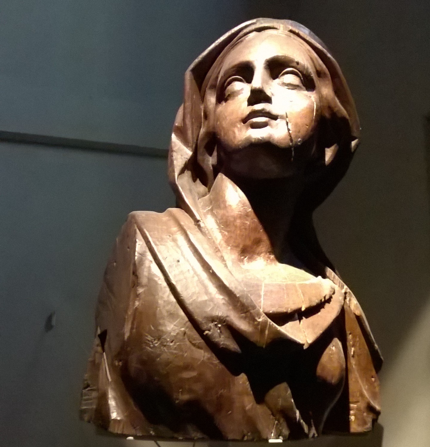
Image: a section from a photoelastic model of turbine disc with a single blade viewed in polarised light to reveal the stress distribution.