Tag Archives: Engineering

Everyday examples contribute to successful learning

Some weeks ago I quoted Adams and Felder [2008] who said that the ‘educational role of faculty [academic staff] is not to impart knowledge; but to design learning environments that support…knowledge acquisition’ [see ‘Creating an evolving learning environment’ on February 21st, 2018].  A correspondent asked how I create a learning environment and, in response, this is the first in a series of posts on the topic that will appear every third week.  The material is taken from a one-day workshop that Pat Campbell [of Campbell-Kibler Associates] and I have given periodically in the USA [supported by NSF ] and UK [supported by HEA] for engineering academics.

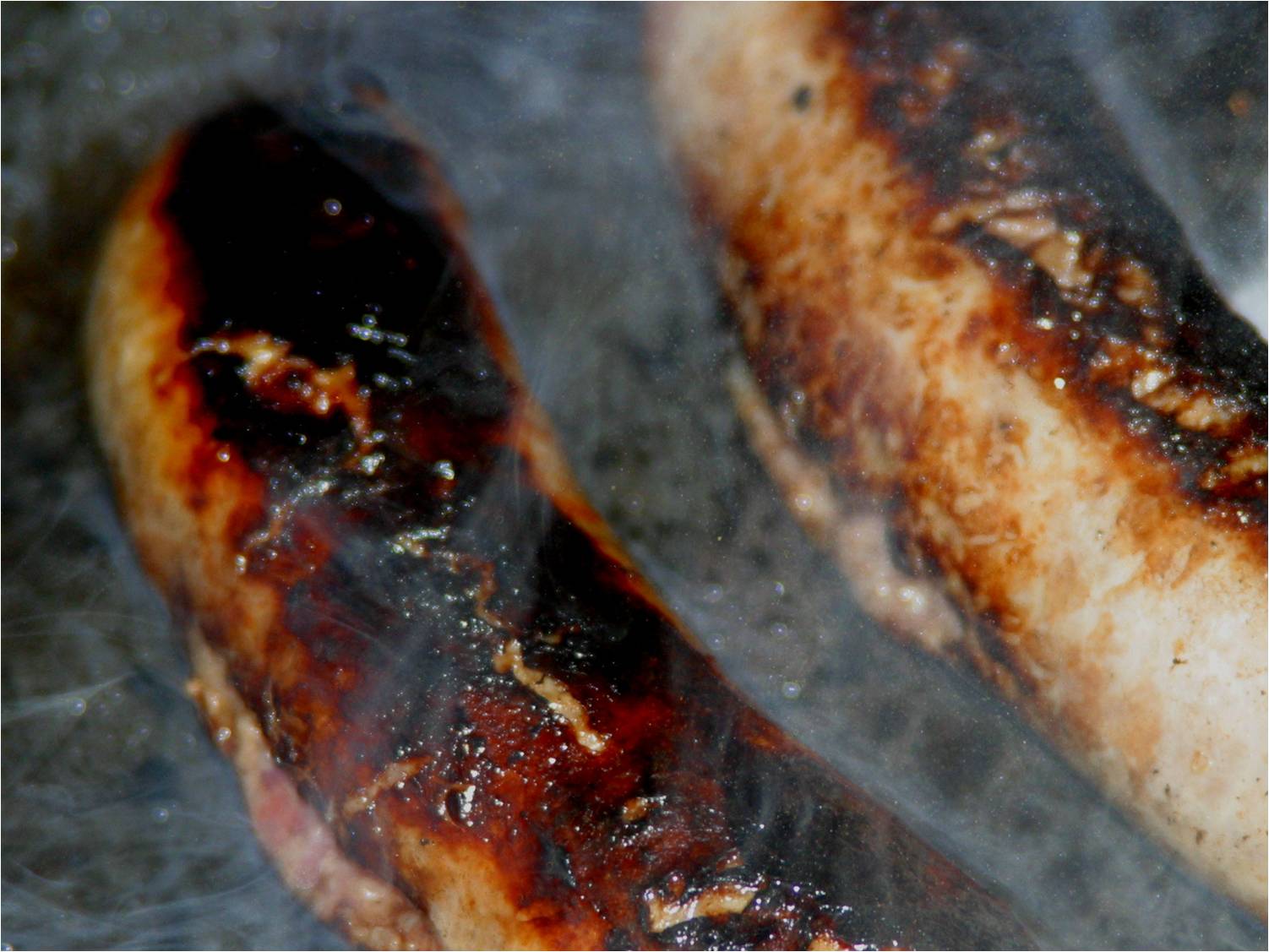
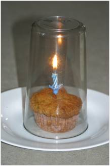
Albert Einstein is reputed to have said that ‘knowledge is experience, everything else is just information’.  I believe that a key task for a university teacher of engineering is to find the common experiences of their students and use them to illustrate engineering principles.  This is relatively straightforward for senior students because they will have taken courses or modules delivered by your colleagues; however, it is more of a challenge for students entering the first year of an engineering programme.  Everyone is unique and a product of their formative conditions, which makes it tricky to identify common experiences that can be used to explain engineering concepts.  The Everyday Engineering Examples, which feature on a page of this blog [https://realizeengineering.blog/everyday-engineering-examples/], were developed to address the need for illustrative situations that would fall into the experience of most, if not all, students.  Two popular examples are using the splits in sausages when you cook them to illustrate two-dimensional stress systems in pressure vessels [see lesson plan S11] and using a glass to extinguish a birthday candle on a cup cake to explain combustion processes [see lesson plan T11].
Everyday Engineering Examples were developed as part of an educational research project, which was funded by the US National Science Foundation [see ENGAGE] and demonstrated that this approach to teaching works.  The project found that significantly more students rated their learning with Everyday Engineering Examples as high or significant than in the control classes independent of the level of difficult involved [Campbell et al. 2008].  So, this is one way in which I create a learning environment that supports knowledge acquisition.  More in future posts…
References

Adams RS & Felder RM, Reframing professional development: A systems approach to preparing engineering educators to educate tomorrow’s engineers. J. Engineering Education, 97(3):230-240, 2008

Campbell PB, Patterson EA, Busch Vishniac I & Kibler T, Integrating Applications in the Teaching of Fundamental Concepts, Proc. 2008 ASEE Annual Conference and Exposition, (AC 2008-499), 2008


CALE #1 [Creating A Learning Environment: a series of posts based on a workshop given periodically by Pat Campbell and Eann Patterson in the USA supported by NSF and the UK supported by HEA]

INSTRUCTIVE research relevance

The Southwest airplane accident last week has been initially attributed to a fatigue crack in a fan blade in the engine.  One of the reasons that this an extremely rare event is the enormous research effort that has been expended on the design, testing and maintenance of the engines and the airframe.  It’s an ongoing research effort to address the trilemma of aircraft that are safe, sustainable and low cost to build and operate.  In collaboration with Strain Solutions Limited, we are in the last year of a three-year project called INSTRUCTIVE which is funded by the Clean Sky 2 programme of the European Commission [see ‘Instructive report and Brexit‘ on March 29th, 2017].   The focus of the research is the development of techniques for use in the aerospace industry to detect the initiation of cracks in the airframe before the crack is visible to the naked eye [see ‘Instructive update‘ on October 4th, 2017].  Laboratory-based techniques exist with this capability and the objective is to transfer the technology to the industrial scale and environment – initially in structural tests performed as part of the design and certification process and perhaps later as part of inspections of aircraft in service.  So far, we have moved from the small components reported in the update posted in October, to a chunk of aircraft fuselage in our lab and we are preparing to participate in a test being conducted by Airbus later this year.

We are also planning a knowledge exchange workshop on ‘Real-time damage tracking in engineering structures’ on November 21st, 2018 at the University of Liverpool’s London campus.  The one-day workshop is being organised in collaboration with the British Society for Strain Measurement.  More details to follow – it will be free!

Image Credit: Powering the 737: CFM56-7 series | by Frans Zwart at https://www.flickr.com/photos/15545136@N06/9719995154  [CC BY-NC-ND 2.0]


Massive engineering

Last month I was at the Photomechanics 2018 conference in Toulouse in France.  Photomechanics is the science of using photons to measure deformation and displacements in anything, from biological cells to whole engineering structures, such as bridges or powerstations [see for example: ‘Counting photons to measure stress‘ posted on November 18th, 2015].  I am interested in the challenges created by the extremes of scale and environmental conditions; although on this occasion we presented our research on addressing the challenges of industrial applications, in the EU projects INSTRUCTIVE [see ‘Instructive update‘ on October 4th, 2017] and MOTIVATE [see ‘Brave New World‘ posted on January 10th, 2018].

It was a small conference without parallel sessions and the organisers were more imaginative than usual in providing us with opportunities for interaction.  At the end of first day of talks, we went on a guided walking tour of old Toulouse.  At the end of second day, we went to the Toulouse Aerospace Museum and had the chance to go onboard Concorde.

I stayed an extra day for an organised tour of the Airbus A380 assembly line.  Only the engine pylons are made in Toulouse.  The rest of the 575-seater plane is manufactured around Europe and arrives in monthly road convoys after travelling by sea to local ports.  The cockpit, centre, tail sections of the double-deck fuselage travel separately on specially-made trucks with each 45m long wing section following on its own transporter.  It takes about a month to assemble these massive sections.  This is engineering on a huge scale performed with laser precision (laser systems are used to align the sections).  The engines are also manufactured elsewhere and transported to Toulouse to be hung on the wings.  The maximum diameter of the Rolls-Royce Trent 900 engines, being attached to the plane we saw, is approximately same as the fuselage diameter of an A320 airplane.

Once the A380 is assembled and its systems tested, then it is flown to another Airbus factory in Germany to be painted and for the cabin to be fitted out to the customer’s specification.  In total, 11 Airbus factories in France, Germany, Spain and the United Kingdom are involved in producing the A380; this does not include the extensive supply chain supporting these factories.  As I toured the assembly line and our guide assailed us with facts and figures about the scale of the operation, I was thinking about why the nuclear power industry across Europe could not collaborate on this scale to produce affordable, identical power stations.  Airbus originated from a political decision in the 1970s to create a globally-competitive European aerospace industry that led to a collaboration between national manufacturers which evolved into the Airbus company.  One vision for fusion energy is a globally dispersed manufacturing venture that would evolve from the consortium that is currently building the ITER experiment and planning the DEMO plant.  However, there does not appear to be any hint that the nuclear fission industry is likely to follow the example of the European aerospace industry to create a globally-competitive industry producing massive pieces of engineering within a strictly regulated environment.

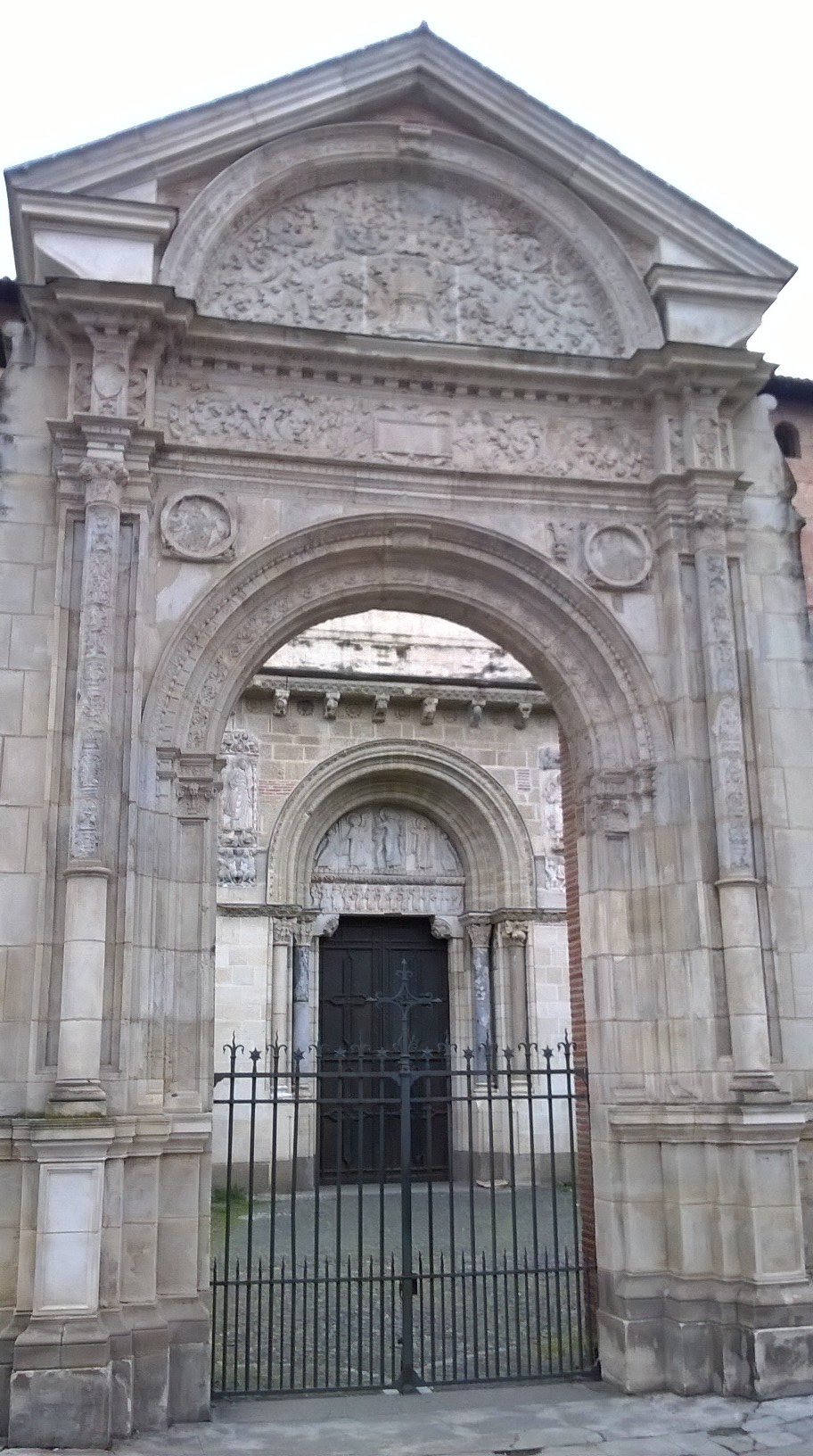
There was no photography allowed at Airbus so today’s photograph is of Basilique Notre-Dame de la Daurade in Toulouse.

Hierarchical modelling in engineering and biology

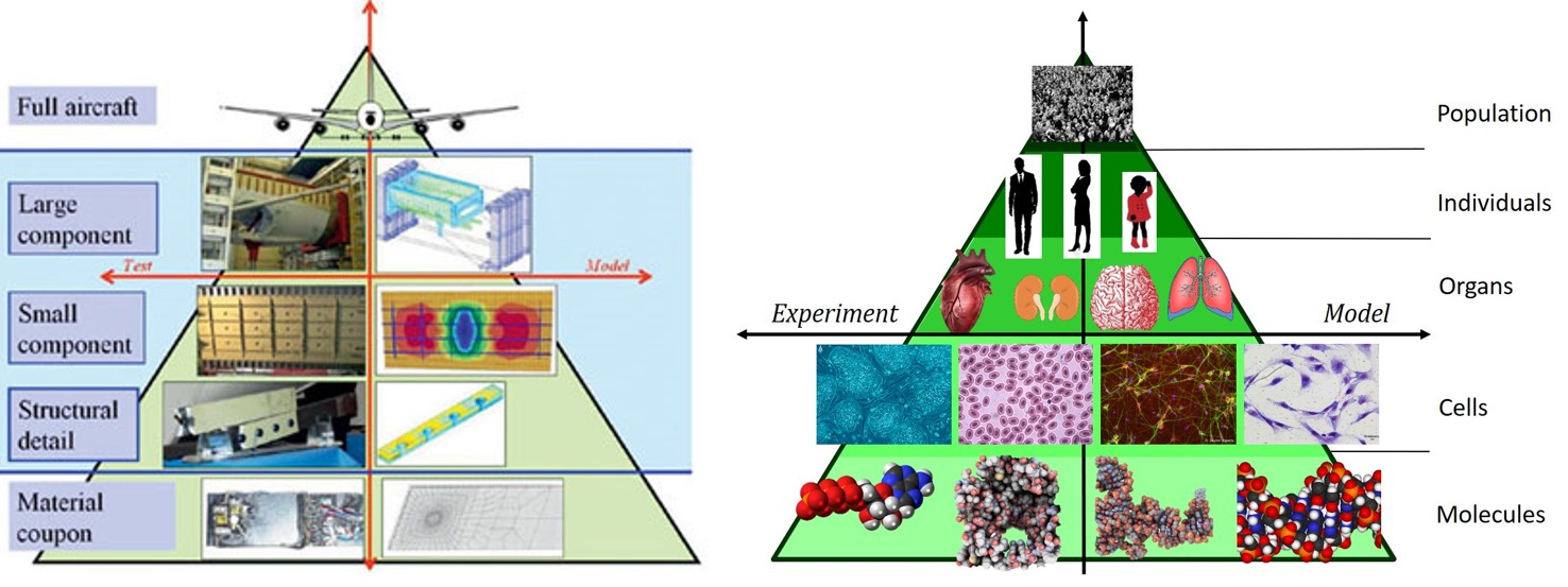
In the 1979 Glenn Harris proposed an analytical hierarchy of models for estimating tactical force effectiveness for the US Army which was represented as a pyramid with four layers with a theatre/campaign simulation at the apex supported by mission level simulations below which was engagement model and engineering models of assets/equipment at the base.  The idea was adopted by the aerospace industry [see the graphic on the left] who place the complete aircraft on the apex supported by systems, sub-systems and components beneath in increasing numbers with the pyramid divided vertically in half to represent physical tests on one side and simulations on the other.  This represents the need to validate predictions from computational models with measurements in the real-world [see post on ‘Model validation‘ on September 18th, 2012]. These diagrams are schematic representations used by engineers to plan and organise the extensive programmes of modelling and physical testing undertaken during the design of new aircraft [see post on ‘Models as fables‘ on March 16th, 2016].  The objective of the MOTIVATE research project is to reduce quantity and increase the quality of the physical tests so that pyramid becomes lop-sided, i.e. the triangle representing the experiments and tests is a much thinner slice than the one representing the modelling and simulations [see post on ‘Brave New World‘ on January 10th, 2018].

At the same time, I am working with colleagues in toxicology on approaches to establishing credibility in predictive models for chemical risk assessment.  I have constructed an equivalent pyramid to represent the system hierarchy which is shown on the right in the graphic.  The challenge is the lack of measurement data in the top left of the pyramid, for both moral and legal reasons, which means that there is very limited real-world data available to confirm the predictions from computational models represented on the right of the pyramid.  In other words, my colleagues in toxicology, and computational biology in general, are where my collaborators in the aerospace industry would like to be while my collaborators in the aerospace want to be where the computational biologists find themselves already.  The challenge is that in both cases a paradigm shift is required from objectivism toward relativism;  since, in the absence of comprehensive real-world measurement data, validation or confirmation of predictions becomes a social process involving judgement about where the predictions lie on a continuum of usefulness.

Sources:

Harris GL, Computer models, laboratory simulators, and test ranges: meeting the challenge of estimating tactical force effectiveness in the 1980’s, US Army Command and General Staff College, May 1979.

Trevisani DA & Sisti AF, Air Force hierarchy of models: a look inside the great pyramid, Proc. SPIE 4026, Enabling Technology for Simulation Science IV, 23 June 2000.

Patterson EA & Whelan MP, A framework to establish credibility of computational models in biology, Progress in Biophysics and Molecular Biology, 129:13-19, 2017.