Tag Archives: mechanics

Holes in fluids

Out-of-focus image from optical microscope of 10 micron diameter polystrene spheres in water

Out-of-focus image from optical microscope of 10 micron diameter polystyrene spheres in water

The holes that I wrote about last week and the week before (post entitled ‘Holes‘ on October 8th)were essentially air-filled holes in a solid plate.  When an in-plane load is applied to the plate it deforms and its surface around the hole becomes curved due to the concentration of stress and light passing through the curved surfaces is deviated to form the caustic.  If you didn’t follow that quick recap on last week then you might want flip back to last week’s post before pressing on!

The reverse situation is a solid in a fluid.  It is difficult to induce stress in a fluid so instead we can use a three-dimensional hole, i.e. a sphere, to generate the curve surface for light to pass through and be deviated.  This is quite an easy experiment to do in an optical microscope with some polystyrene spheres floating in distilled water with the microscope slightly out of focus you get bright caustics.  And if you take a series of photographs (the x-y plane) with the microscope objective lens at different heights (z-value) it is possible to reconstruct the three-dimensional shape of the caustic by taking the intensity or greyscale values along the centre line of each image and using them all to create new image of the x-z and, or y-z plane, as shown in the picture.

Well done if you have got this far and are still with me!  I hope you can at least enjoy the pictures.  By the way the particle in the images is about the same diameter as a human hair.
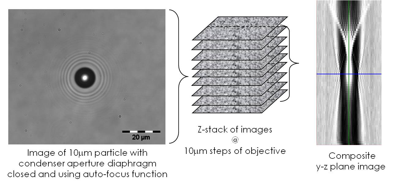
Image in optical microscope of polystrene particle in water (left), series of images at different positions of microscope objective (centre) and artificial image created from greyscale data along centre-lines of image series (right).

Image in optical microscope of polystyrene particle in water (left), series of images at different positions of microscope objective (centre) and artificial image created from greyscale data along centre-lines of image series (right).

Source:

Patterson, E.A., & Whelan, M.P., Tracking nanoparticles in an optical microscope using caustics, Nanotechnology, 19(10): 105502, 2008.

Caustics

caustic_hole

White light caustic of 4mm diameter hole in 6mm (PMMA) plate subject to 3kN tension

As children many of us have burnt a hole (yes, tenuous link to last week’s post on ‘Holes’) in a piece of paper by focussing the sun’s rays with a magnifying glass. If you move the glass up or down and tilt it slightly then the sun’s rays will not be focussed on a spot and instead you see a complex spiralling pattern of light. This pattern is caused by the rays being bent by their passage through different sections of the curved glass. The same type of pattern, known as a caustic, appears on the bottom of your bath when you let (clean) water run out down the plug-hole if you have spotlights above the bath. This caustic is produced by the light rays from the spotlight being bent by varying degrees depending on where they pass through the vortex formed by the water spinning down the hole.  Caustics can also be produced when light passes through a glass of water or on the bottom of an outdoor swimming pool in bright sunlight.

The top picture shows the caustic formed by light passing through a transparent plate with a hole when the plate is stretched in the vertical direction. The load in the plate has to flow around the hole where it ‘bunches up’ or concentrates (see last week’s post entitled ‘Holes’) which causes high levels of local deformation with the plate thinning non-linearly at the intersection of the hole circumference and horizontal diameter. When the light passes through the deformed region it is deviated by amount dependent on the local thinning and forms the pattern shown.

This is not a totally abstract phenomenon because the same mechanism of thinning occurs at the tip of cracks as a result of the very high stress concentration at the sharp crack tip, as shown schematically in the diagram below. So we can evaluate the stress concentration by measuring the caustic it generates; it is even possible to predict in which direction the crack will grow next.

Schematic diagram of transparent plate with a crack loaded vertically in tension (left), light ray tracings through the cracked region (centre) and caustic formed on a screen (right).

Schematic diagram of transparent plate with a crack loaded vertically in tension (left), light ray tracings through the cracked region (centre) and caustic formed on a screen (right).

For information:

Carazo-Alvarez, J.D., Patterson, E.A., 1999, ‘A general method for automated analysis of caustics’, Optics & Lasers in Engng., 32: 95-110.

http://lgg.epfl.ch/caustics/

Holes

Holes, little circular ones. There are billions of them in engineering machines and structures. There are more than a million in a jumbo jet alone. Some of them are filled with fasteners, such as bolts and rivets, others are empty to allow fluids to flow through a surface. Load passing through a structure has to flow around holes, especially when they are empty, and the contours of stress bunch up around a hole to form a stress concentration. For a small hole in a very large plate, the stress on the circumference of the hole is three times the level found in the absence of the hole. This concentration increases for bigger holes or smaller plates, so that holes are a potential source of failure – that’s why sheets of stamps are perforated with lines of holes.

A hole can also stop a failure. For instance a crack extending under repeated loading will often stop when it grows into a hole because the ‘sharpness’ of the crack tip is blunted by the roundness of the hole. Engineers sometimes deliberately drill a hole at a crack tip to arrest its progress. So, holes can be both an engineer’s friend and foe.

Conflict Resolution

conflict pyramidEngineers need to be experts in resolving conflicts…

Every man-made device that moves required energy to make it and uses energy when it moves. Heavier devices have greater inertia than small ones and hence more energy is needed to set them in motion – think about peddling an old-fashioned steel-framed bike compared to a modern alloy one. So, designing for sustainability requires engineers to minimise the quantity of raw materials and energy used to manufacture a device AND to minimize its weight if the device moves as part of its function.

Now, here comes the conflict.

Sustainability also implies that devices should have a long, maintenance-free service life so that resources used in maintenance and replacement are minimized. Service life is usually limited by fatigue and, or wear and the probability of these failure mechanisms occurring can be reduced by lowering stress levels. However, stress is inversely proportional to cross-section area and so can be reduced by adding material, i.e. increasing the mass of the device which will also increase its inertia, or resistance to motion. The probability of failure can be reduced by using stronger, more sophisticated materials that are lightweight and almost always more expensive, e.g. composites. Customers also want performance and additional expense might be acceptable if it is accompanied by additional performance – some people will pay for a carbon-fibre frame for their bicycle. Elegant engineering design requires resolution of the conflict between cost, safety and reliability, performance and sustainability.

This is why engineers are trained in conflict resolution or as it is more commonly known: problem-solving.