Tag Archives: strain

Caustics

caustic_hole

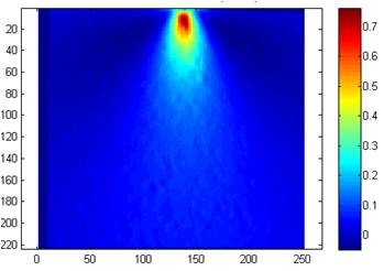
White light caustic of 4mm diameter hole in 6mm (PMMA) plate subject to 3kN tension

As children many of us have burnt a hole (yes, tenuous link to last week’s post on ‘Holes’) in a piece of paper by focussing the sun’s rays with a magnifying glass. If you move the glass up or down and tilt it slightly then the sun’s rays will not be focussed on a spot and instead you see a complex spiralling pattern of light. This pattern is caused by the rays being bent by their passage through different sections of the curved glass. The same type of pattern, known as a caustic, appears on the bottom of your bath when you let (clean) water run out down the plug-hole if you have spotlights above the bath. This caustic is produced by the light rays from the spotlight being bent by varying degrees depending on where they pass through the vortex formed by the water spinning down the hole.  Caustics can also be produced when light passes through a glass of water or on the bottom of an outdoor swimming pool in bright sunlight.

The top picture shows the caustic formed by light passing through a transparent plate with a hole when the plate is stretched in the vertical direction. The load in the plate has to flow around the hole where it ‘bunches up’ or concentrates (see last week’s post entitled ‘Holes’) which causes high levels of local deformation with the plate thinning non-linearly at the intersection of the hole circumference and horizontal diameter. When the light passes through the deformed region it is deviated by amount dependent on the local thinning and forms the pattern shown.

This is not a totally abstract phenomenon because the same mechanism of thinning occurs at the tip of cracks as a result of the very high stress concentration at the sharp crack tip, as shown schematically in the diagram below. So we can evaluate the stress concentration by measuring the caustic it generates; it is even possible to predict in which direction the crack will grow next.

Schematic diagram of transparent plate with a crack loaded vertically in tension (left), light ray tracings through the cracked region (centre) and caustic formed on a screen (right).

Schematic diagram of transparent plate with a crack loaded vertically in tension (left), light ray tracings through the cracked region (centre) and caustic formed on a screen (right).

For information:

Carazo-Alvarez, J.D., Patterson, E.A., 1999, ‘A general method for automated analysis of caustics’, Optics & Lasers in Engng., 32: 95-110.

http://lgg.epfl.ch/caustics/

Conflict Resolution

conflict pyramidEngineers need to be experts in resolving conflicts…

Every man-made device that moves required energy to make it and uses energy when it moves. Heavier devices have greater inertia than small ones and hence more energy is needed to set them in motion – think about peddling an old-fashioned steel-framed bike compared to a modern alloy one. So, designing for sustainability requires engineers to minimise the quantity of raw materials and energy used to manufacture a device AND to minimize its weight if the device moves as part of its function.

Now, here comes the conflict.

Sustainability also implies that devices should have a long, maintenance-free service life so that resources used in maintenance and replacement are minimized. Service life is usually limited by fatigue and, or wear and the probability of these failure mechanisms occurring can be reduced by lowering stress levels. However, stress is inversely proportional to cross-section area and so can be reduced by adding material, i.e. increasing the mass of the device which will also increase its inertia, or resistance to motion. The probability of failure can be reduced by using stronger, more sophisticated materials that are lightweight and almost always more expensive, e.g. composites. Customers also want performance and additional expense might be acceptable if it is accompanied by additional performance – some people will pay for a carbon-fibre frame for their bicycle. Elegant engineering design requires resolution of the conflict between cost, safety and reliability, performance and sustainability.

This is why engineers are trained in conflict resolution or as it is more commonly known: problem-solving.

Setting standards

cenLast week I wrote about digital image correlation as a method for measuring surface strain and displacement fields.  The simplicity and modest cost of the equipment required combined with the quality and quantity of the results is revolutionizing the field of experimental mechanics.  It also has the potential to do the same in computational mechanics by enabling more comprehensive validation of models and thus enhancing the credibility and confidence in engineering simulations.  I have written and lectured on this topic many times, see for instance my post of September 17th, 2012 entitled ‘Model credibility’ or  http://sdj.sagepub.com/content/48/1.toc

At the moment, I am chair of a CEN workshop WS71 that is developing a precursor to a standard on validation of computational solid mechanics models.  To inform our deliberations, we have organised an Inter-Laboratory Study (ILS) to allow people to try out the proposed validation protocol and give us feedback.   If you would like to have a go then download the information pack.  You don’t need to do any experiments or modelling, just try the validation procedure with some of the data sets provided.  The more engineers that participate in the ILS then the better that the final CEN document is likely to be; so if you know someone who might be interested then forward this blog to them or just send them the link.

Displacement field measured using image correlation for metal wedge indenting a rubber block

Displacement field measured using digital image correlation for a metal wedge indenting a rubber block

CEN WS71: http://www.cen.eu/cen/Sectors/TechnicalCommitteesWorkshops/Workshops/Pages/WS71VANESSA.aspx

EU FP7 project VANESSA: www.engineeringvalidation.org

For information on the data field shown to the right see: http://sdj.sagepub.com/content/49/2/112.abstract

256 shades of grey

bonnet panelEngineers are increasingly using digital photographs with 256 shades of grey to measure displacement of structural components.  The technique is known as Digital Image Correlation and is the most common way to measure the deformation of engineering structures and components in a laboratory, and increasingly in the field.  DIC provides maps of the displacement of the component surface from which the strain field can be calculated and which in turn allows engineers to assess the behaviour and likely failure modes of the component.  DIC is beginning to revolutionise the way in which we validate computational mechanics models.

DIC involves capturing ‘before’ and ‘after’ images of the component surface while load is applied.  If the surface has a random pattern, which is often created by spray-painting black speckles onto a white background, then it is possible to track the movement of the pattern as the surface moves and deforms.  The images are usually recorded as intensity maps defined by 256 shades of grey or grey levels from white through to black.  A mathematical signature is assigned to facets or sub-images of the intensity map in the ‘before’ image and a correlation algorithm uses the signature to recognise the facet in the ‘after’ image.  The positions of the centre of the facet in the ‘before’ and ‘after’ images indicates the displacement of the corresponding area of the component surface.  Two cameras can be used to provide stereoscopic vision and information on displacements in all directions.

The picture shows a car bonnet or hood panel in a test frame in a laboratory prior to an impact test with a random speckle pattern on the surface to allow DIC to be performed using high-speed cameras. For more details see: Burguete et al , 2013, J. Strain Analysis, doi:10.1177/0309324713498074 at http://sdj.sagepub.com/content/early/2013/09/19/0309324713498074.full.pdf+html

For detailed explanations of DIC try the monograph by Professor Mike Sutton and his colleagues [link.springer.com/content/pdf/bfm%3A978-0-387-78747-3%2F1.pdf] or the chapter on DIC in Optical Methods for Solid Mechanics by Pramod Rastogi and Erwin Hack [http://eu.wiley.com/WileyCDA/WileyTitle/productCd-3527411119.html].

For some applications see the special issue on DIC of the Journal of Strain Analysis for Engineering Design [http://sdj.sagepub.com/content/43/8.toc].