Category Archives: FACTS

Holes in fluids

Out-of-focus image from optical microscope of 10 micron diameter polystrene spheres in water

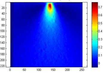
Out-of-focus image from optical microscope of 10 micron diameter polystyrene spheres in water

The holes that I wrote about last week and the week before (post entitled ‘Holes‘ on October 8th)were essentially air-filled holes in a solid plate.  When an in-plane load is applied to the plate it deforms and its surface around the hole becomes curved due to the concentration of stress and light passing through the curved surfaces is deviated to form the caustic.  If you didn’t follow that quick recap on last week then you might want flip back to last week’s post before pressing on!

The reverse situation is a solid in a fluid.  It is difficult to induce stress in a fluid so instead we can use a three-dimensional hole, i.e. a sphere, to generate the curve surface for light to pass through and be deviated.  This is quite an easy experiment to do in an optical microscope with some polystyrene spheres floating in distilled water with the microscope slightly out of focus you get bright caustics.  And if you take a series of photographs (the x-y plane) with the microscope objective lens at different heights (z-value) it is possible to reconstruct the three-dimensional shape of the caustic by taking the intensity or greyscale values along the centre line of each image and using them all to create new image of the x-z and, or y-z plane, as shown in the picture.

Well done if you have got this far and are still with me!  I hope you can at least enjoy the pictures.  By the way the particle in the images is about the same diameter as a human hair.

Image in optical microscope of polystrene particle in water (left), series of images at different positions of microscope objective (centre) and artificial image created from greyscale data along centre-lines of image series (right).

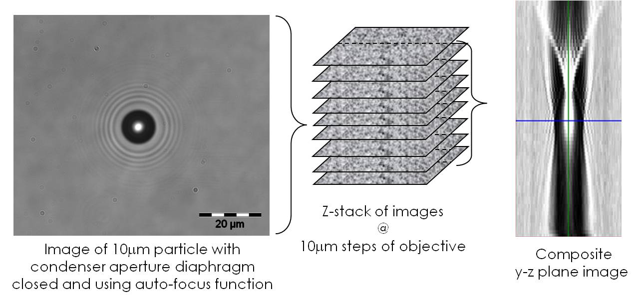
Image in optical microscope of polystyrene particle in water (left), series of images at different positions of microscope objective (centre) and artificial image created from greyscale data along centre-lines of image series (right).

Source:

Patterson, E.A., & Whelan, M.P., Tracking nanoparticles in an optical microscope using caustics, Nanotechnology, 19(10): 105502, 2008.

Setting standards

cenLast week I wrote about digital image correlation as a method for measuring surface strain and displacement fields.  The simplicity and modest cost of the equipment required combined with the quality and quantity of the results is revolutionizing the field of experimental mechanics.  It also has the potential to do the same in computational mechanics by enabling more comprehensive validation of models and thus enhancing the credibility and confidence in engineering simulations.  I have written and lectured on this topic many times, see for instance my post of September 17th, 2012 entitled ‘Model credibility’ or  http://sdj.sagepub.com/content/48/1.toc

At the moment, I am chair of a CEN workshop WS71 that is developing a precursor to a standard on validation of computational solid mechanics models.  To inform our deliberations, we have organised an Inter-Laboratory Study (ILS) to allow people to try out the proposed validation protocol and give us feedback.   If you would like to have a go then download the information pack.  You don’t need to do any experiments or modelling, just try the validation procedure with some of the data sets provided.  The more engineers that participate in the ILS then the better that the final CEN document is likely to be; so if you know someone who might be interested then forward this blog to them or just send them the link.

Displacement field measured using image correlation for metal wedge indenting a rubber block

Displacement field measured using digital image correlation for a metal wedge indenting a rubber block

CEN WS71: http://www.cen.eu/cen/Sectors/TechnicalCommitteesWorkshops/Workshops/Pages/WS71VANESSA.aspx

EU FP7 project VANESSA: www.engineeringvalidation.org

For information on the data field shown to the right see: http://sdj.sagepub.com/content/49/2/112.abstract

Toxic nanoparticles?

My obsession with kinematics and kinetics over the past few posts is connected to my recent trip to Italy [see my post last week] as part of a research project on the mechanics of nanoparticles.  We are interested in the toxicological effect of nanoparticles on biological cells.  Nanoparticles are finding lots of applications but we don’t completely understand their interaction with cells and organs in the body.  We are interested in particles with diameters around 10 nanometres.  The diameter of a human hair is 10,000 times bigger.  The small size of these particles has potential implications for their kinematics and kinetics as they move through the body.  We know that protein molecules can attach themselves to nanoparticles forming a corona and as part of our research we are looking at how that influences the motion of the particle.  For instance, it might be appropriate to use kinematics for a spherical metallic nanoparticle but kinetics for one with a corona.

Some of you might be thinking, why go to Italy?  Well, other than for the coffee, I have been working with a colleague there for some time on methods of tracking nanoparticles that are below the resolution of optical microscopes.  We have named the technique ‘nanoscopy’ and it allows us to look at live cells and nanoparticles simultaneously without damaging the cell.  So our current research is an extension of the earlier work (see the two papers referenced below).  Of course the more basic answer is that we get on and are very productive together.

BTW – we can’t ‘see’ our nanoparticles because visible light has wavelengths about fifty times larger than the particles, so light waves pass single particles without being reflected into our eyes or camera.  However, a particle does disturb the light wave and produce a weak optical signature, which we utilise in nanoscopy.

Research papers available on-line at:

http://onlinelibrary.wiley.com/doi/10.1002/smll.200800703/abstract

http://onlinelibrary.wiley.com/doi/10.1111/j.1365-2818.2011.03491.x/abstract

Model validation

Front cover of ASME V&V 10-2006, Guide for verification and validation in computational solid mechanics, American Society of Mechanical Engineers, New York, 2006.

Why is validation important?  Validation of computational mechanics models is defined as ‘determining the degree to which a model is an accurate representation of the real world from the perspective of the intended uses of the model’, according to  ASME V&V 10-2006.  So, the validation of models of structural integrity for engineering design provides information about the degree to which the simulation results from the model can be believed.  This in turn helps in making decisions about how little material, and in what configuration, should be used to create elegant, sustainable designs that are unlikely to fail. So validation of computational mechanics models is an essential step in solving the ‘two earths’ dilemma (see post on August 13th, 2012).