Tag Archives: mechanics

March Madness

basketballSome of you will be familiar with ‘March Madness’ which starts next week.  It is a couple of weeks in March when US universities play a knockout basketball competition.  At Michigan State University, where I used to be a professor, there would be huge disappointed if we did not make it into the final sixteen and great excitement if we were in the final four or even the final.

Basketballs can be a useful, and in the USA in March topical, prop to use in teaching dynamics.  In the lesson plan below angular momentum is used to investigate a basketball rolling over an obstacle, which could be someone’s foot rather than wooden block used in the example.  Of course, with 91 days to go until the start of the FIFA World Cup in Brazil, you could easily switch to a football.

5EplanNoD9_Impulse&momentum_methods

See the Everyday Examples page on this blog for more lesson plans and more background on Everyday Examples.

Smart machines

violin
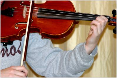
My enthusiasm for the concert we went to some weeks ago is only just beginning to fade [see Rhapsody in Blue posted on 5th February, 2014].  I have one of Michel Camilo’s pieces still going around in head [listen here].  On the subject of playing the piano, people are trying to build robots that can play the piano using rubbery fingers although they have had more success with a robot that can play a violin [see this Youtube clip].

These robots might be clunky or primitive compared to a maestro like Michel Camilo, but nevertheless smart machines are coming.  Professor Noriko Arai is developing a computer, called Todai-Kun, that could ace college entrance exams.  She hopes that by 2021 Todai-Kun will pass the entrance exam for Tokyo University, which is the top university in Japan.  It is tough for graduates to find jobs at the moment, so imagine what it will be like if computers are as smart as graduates!

Mechanisation destroyed jobs on the farm, robots have replaced assembly-line workers and now smart computers are going to replace white collar workers.  In the future, if you want a well-paid job you are likely to need niche skills that involve a combination of creativity, innovation, problem-solving and leadership.  I am probably biased but that sounds like a professional engineer.

In the same context, David Brooks has suggested that, what he calls the ’emotive traits’ will be required for success, i.e. a voracious lust of understanding, an enthusiasm for work, the ability to grasp the gist and an empathetic sensitivity for what will attract attention, which with the exception of the last one also sound like the attributes of a professional engineer.

I have used the violin playing robot as the focus for a 5E lesson plan on the Kinematics of Rigid bodies in 3-dimensions see: 5EplanNoD10_Kinematics_of_rigid_bodies_in_3D .  Not quite an ‘Everyday Example’ but one with which many students can connect.

Sources:

http://www.nytimes.com/2013/12/30/world/asia/computers-jump-to-the-head-of-the-class.html?_r=0

http://www.nytimes.com/2014/02/04/opinion/brooks-what-machines-cant-do.html?_r=0

Setting standards

cenLast week I wrote about digital image correlation as a method for measuring surface strain and displacement fields.  The simplicity and modest cost of the equipment required combined with the quality and quantity of the results is revolutionizing the field of experimental mechanics.  It also has the potential to do the same in computational mechanics by enabling more comprehensive validation of models and thus enhancing the credibility and confidence in engineering simulations.  I have written and lectured on this topic many times, see for instance my post of September 17th, 2012 entitled ‘Model credibility’ or  http://sdj.sagepub.com/content/48/1.toc

At the moment, I am chair of a CEN workshop WS71 that is developing a precursor to a standard on validation of computational solid mechanics models.  To inform our deliberations, we have organised an Inter-Laboratory Study (ILS) to allow people to try out the proposed validation protocol and give us feedback.   If you would like to have a go then download the information pack.  You don’t need to do any experiments or modelling, just try the validation procedure with some of the data sets provided.  The more engineers that participate in the ILS then the better that the final CEN document is likely to be; so if you know someone who might be interested then forward this blog to them or just send them the link.

Displacement field measured using image correlation for metal wedge indenting a rubber block

Displacement field measured using digital image correlation for a metal wedge indenting a rubber block

CEN WS71: http://www.cen.eu/cen/Sectors/TechnicalCommitteesWorkshops/Workshops/Pages/WS71VANESSA.aspx

EU FP7 project VANESSA: www.engineeringvalidation.org

For information on the data field shown to the right see: http://sdj.sagepub.com/content/49/2/112.abstract

256 shades of grey

bonnet panelEngineers are increasingly using digital photographs with 256 shades of grey to measure displacement of structural components.  The technique is known as Digital Image Correlation and is the most common way to measure the deformation of engineering structures and components in a laboratory, and increasingly in the field.  DIC provides maps of the displacement of the component surface from which the strain field can be calculated and which in turn allows engineers to assess the behaviour and likely failure modes of the component.  DIC is beginning to revolutionise the way in which we validate computational mechanics models.

DIC involves capturing ‘before’ and ‘after’ images of the component surface while load is applied.  If the surface has a random pattern, which is often created by spray-painting black speckles onto a white background, then it is possible to track the movement of the pattern as the surface moves and deforms.  The images are usually recorded as intensity maps defined by 256 shades of grey or grey levels from white through to black.  A mathematical signature is assigned to facets or sub-images of the intensity map in the ‘before’ image and a correlation algorithm uses the signature to recognise the facet in the ‘after’ image.  The positions of the centre of the facet in the ‘before’ and ‘after’ images indicates the displacement of the corresponding area of the component surface.  Two cameras can be used to provide stereoscopic vision and information on displacements in all directions.

The picture shows a car bonnet or hood panel in a test frame in a laboratory prior to an impact test with a random speckle pattern on the surface to allow DIC to be performed using high-speed cameras. For more details see: Burguete et al , 2013, J. Strain Analysis, doi:10.1177/0309324713498074 at http://sdj.sagepub.com/content/early/2013/09/19/0309324713498074.full.pdf+html

For detailed explanations of DIC try the monograph by Professor Mike Sutton and his colleagues [link.springer.com/content/pdf/bfm%3A978-0-387-78747-3%2F1.pdf] or the chapter on DIC in Optical Methods for Solid Mechanics by Pramod Rastogi and Erwin Hack [http://eu.wiley.com/WileyCDA/WileyTitle/productCd-3527411119.html].

For some applications see the special issue on DIC of the Journal of Strain Analysis for Engineering Design [http://sdj.sagepub.com/content/43/8.toc].