Category Archives: mechanics

Setting standards

cenLast week I wrote about digital image correlation as a method for measuring surface strain and displacement fields.  The simplicity and modest cost of the equipment required combined with the quality and quantity of the results is revolutionizing the field of experimental mechanics.  It also has the potential to do the same in computational mechanics by enabling more comprehensive validation of models and thus enhancing the credibility and confidence in engineering simulations.  I have written and lectured on this topic many times, see for instance my post of September 17th, 2012 entitled ‘Model credibility’ or  http://sdj.sagepub.com/content/48/1.toc

At the moment, I am chair of a CEN workshop WS71 that is developing a precursor to a standard on validation of computational solid mechanics models.  To inform our deliberations, we have organised an Inter-Laboratory Study (ILS) to allow people to try out the proposed validation protocol and give us feedback.   If you would like to have a go then download the information pack.  You don’t need to do any experiments or modelling, just try the validation procedure with some of the data sets provided.  The more engineers that participate in the ILS then the better that the final CEN document is likely to be; so if you know someone who might be interested then forward this blog to them or just send them the link.
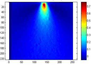
Displacement field measured using image correlation for metal wedge indenting a rubber block

Displacement field measured using digital image correlation for a metal wedge indenting a rubber block

CEN WS71: http://www.cen.eu/cen/Sectors/TechnicalCommitteesWorkshops/Workshops/Pages/WS71VANESSA.aspx

EU FP7 project VANESSA: www.engineeringvalidation.org

For information on the data field shown to the right see: http://sdj.sagepub.com/content/49/2/112.abstract

256 shades of grey

bonnet panelEngineers are increasingly using digital photographs with 256 shades of grey to measure displacement of structural components.  The technique is known as Digital Image Correlation and is the most common way to measure the deformation of engineering structures and components in a laboratory, and increasingly in the field.  DIC provides maps of the displacement of the component surface from which the strain field can be calculated and which in turn allows engineers to assess the behaviour and likely failure modes of the component.  DIC is beginning to revolutionise the way in which we validate computational mechanics models.

DIC involves capturing ‘before’ and ‘after’ images of the component surface while load is applied.  If the surface has a random pattern, which is often created by spray-painting black speckles onto a white background, then it is possible to track the movement of the pattern as the surface moves and deforms.  The images are usually recorded as intensity maps defined by 256 shades of grey or grey levels from white through to black.  A mathematical signature is assigned to facets or sub-images of the intensity map in the ‘before’ image and a correlation algorithm uses the signature to recognise the facet in the ‘after’ image.  The positions of the centre of the facet in the ‘before’ and ‘after’ images indicates the displacement of the corresponding area of the component surface.  Two cameras can be used to provide stereoscopic vision and information on displacements in all directions.

The picture shows a car bonnet or hood panel in a test frame in a laboratory prior to an impact test with a random speckle pattern on the surface to allow DIC to be performed using high-speed cameras. For more details see: Burguete et al , 2013, J. Strain Analysis, doi:10.1177/0309324713498074 at http://sdj.sagepub.com/content/early/2013/09/19/0309324713498074.full.pdf+html

For detailed explanations of DIC try the monograph by Professor Mike Sutton and his colleagues [link.springer.com/content/pdf/bfm%3A978-0-387-78747-3%2F1.pdf] or the chapter on DIC in Optical Methods for Solid Mechanics by Pramod Rastogi and Erwin Hack [http://eu.wiley.com/WileyCDA/WileyTitle/productCd-3527411119.html].

For some applications see the special issue on DIC of the Journal of Strain Analysis for Engineering Design [http://sdj.sagepub.com/content/43/8.toc].

Toxic nanoparticles?

My obsession with kinematics and kinetics over the past few posts is connected to my recent trip to Italy [see my post last week] as part of a research project on the mechanics of nanoparticles.  We are interested in the toxicological effect of nanoparticles on biological cells.  Nanoparticles are finding lots of applications but we don’t completely understand their interaction with cells and organs in the body.  We are interested in particles with diameters around 10 nanometres.  The diameter of a human hair is 10,000 times bigger.  The small size of these particles has potential implications for their kinematics and kinetics as they move through the body.  We know that protein molecules can attach themselves to nanoparticles forming a corona and as part of our research we are looking at how that influences the motion of the particle.  For instance, it might be appropriate to use kinematics for a spherical metallic nanoparticle but kinetics for one with a corona.

Some of you might be thinking, why go to Italy?  Well, other than for the coffee, I have been working with a colleague there for some time on methods of tracking nanoparticles that are below the resolution of optical microscopes.  We have named the technique ‘nanoscopy’ and it allows us to look at live cells and nanoparticles simultaneously without damaging the cell.  So our current research is an extension of the earlier work (see the two papers referenced below).  Of course the more basic answer is that we get on and are very productive together.

BTW – we can’t ‘see’ our nanoparticles because visible light has wavelengths about fifty times larger than the particles, so light waves pass single particles without being reflected into our eyes or camera.  However, a particle does disturb the light wave and produce a weak optical signature, which we utilise in nanoscopy.

Research papers available on-line at:

http://onlinelibrary.wiley.com/doi/10.1002/smll.200800703/abstract

http://onlinelibrary.wiley.com/doi/10.1111/j.1365-2818.2011.03491.x/abstract

Sweeping Kinetics

Last week I left the rubbish on the streets and encouraged you to make a mess in the classroom.  Partly because kinematics does not help us to analyse the forces involved in sweeping rubbish or, more glamorously, an ice hockey puck.  This is the realm of kinetics in which we need to consider the forces acting on objects to cause or impede their motion, such as the push from a broom and the friction against the pavement.  See the 5E lesson plan attached for more details on how Newton’s laws of motion can be applied in these situations.

You might be thinking ‘why should engineers be interested in forces involved in sweeping rubbish?’  Well, it might not be as glamorous as designing sports equipment but someone has to design street sweeping machines that keep our towns and cities clean and it is arguably more beneficial to society and the environment.  Of course, it would be better for the environment if we didn’t drop rubbish that needed sweeping but that’s another post…

5EplanNoD2_force&acceleration

For more on 5E lesson plans see: my post entitled ‘Disease of the modern age’ on June 26th, 2013 and ‘Sizzling Sausages’ on July 3rd, 2013.

For a set of videos on kinetics try: http://www.khanacademy.org/science/physics/forces-newtons-laws