Track of the Brownian motion of a 50 nanometre diameter particle in a fluid.
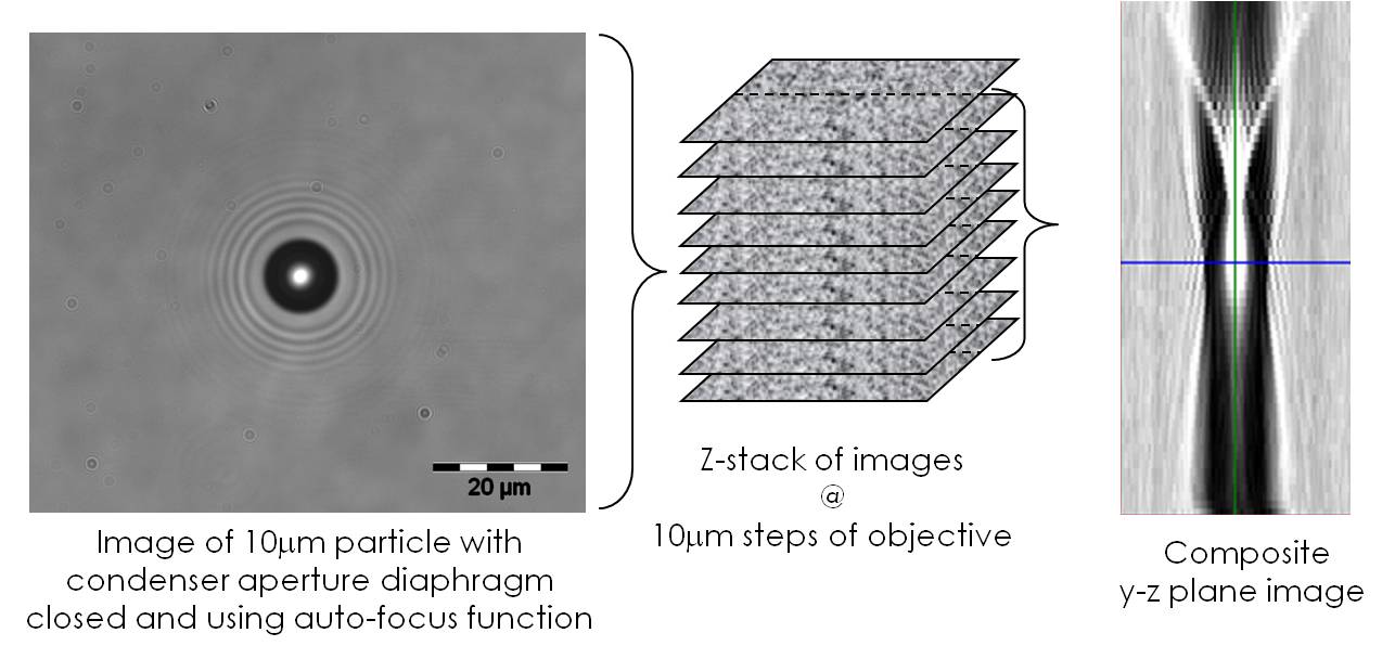
Nanoparticles are being used in a myriad of applications including sunscreen creams, sports equipment and even to study the stickiness of snot! By definition, nanoparticles should have one dimension less than 100 nanometres, which is one thousandth of the thickness of a human hair. Some nanoparticles are toxic to humans and so scientists are studying the interaction of nanoparticles with human cells. However, a spherical nanoparticle is smaller than the wavelength length of visible light and so is invisible in a conventional optical microscope used by biologists. We can view nanoparticles using a scanning electron microscope but the electron beam damages living cells so this is not a good solution. An alternative is to adjust an optical microscope so that the nanoparticles produce caustics [see post entitled ‘Caustics’ on October 15th, 2014] many times the size of the particle. These ‘adjustments’ involve closing an aperture to produce a pin-hole source of illumination and introducing a filter that only allows through a narrow band of light wavelengths. An optical microscope adjusted in this way is called a ‘nanoscope’ and with the addition of a small oscillator on the microscope objective lens can be used to track nanoparticles using the technique described in last week’s post entitled ‘Holes in liquid‘.
The smallest particles that we have managed to observe using this technique were gold particles of diameter 3 nanometres , or about 1o atoms in diameter dispersed in a liquid.
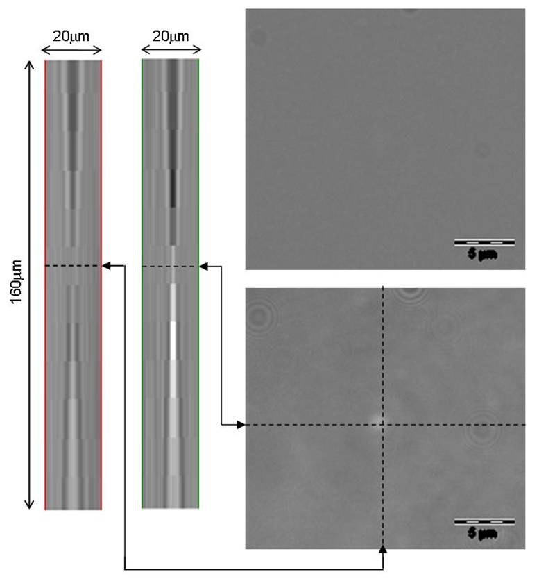
Image of 3nm diameter gold particle in a conventional optical microscope (top right), in a nanoscope (bottom right) and composite images in the z-direction of the caustic formed in the nanoscope (left).
Sources: